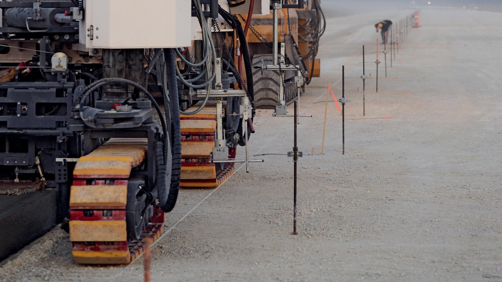
Automatic height and lateral slope control


Height control (leveling) controls the installation height of the concrete profile in relation to a reference. Traditionally, slipform pavers achieve longitudinal and height control via mechanical probing of stringlines.
However, for some years now, 3D control without stringlines has also been proven to be effective, and in some cases it is already a requirement for the awarding of a project. That is because, compared to control via a stringline, 3D control delivers many advantages – for instance, the ideal installation line is not transferred via a string to the real construction site, rather it exists as a model in the computer. This digital site model helps to define the target positions of the machine, and measurement systems – e.g., the motorized Total Station and Prisma –monitor the actual positions. This makes producing any concrete profiles easy, economical, and precise.
Before installation, a stringline is accurately positioned and tensioned. It serves as a reference for the desired installation height of the concrete profile to be produced. Normally, for height control (leveling), two separate sensors mounted on the paver are in contact with the stringline – one sensor for the front chassis and another for the rear. During forward motion of the paver, each sensor probes the stringline and continuously sends related height information to the machine's control system. This height information, however, does not contain absolute values, but only deviations from the target value of the stringline.
Accordingly, the control system takes the measurement results, and in case of deviation it controls the relevant hydraulic cylinders via valves, which corrects the deviation through the machine's height adjustment including the slipform paver. The described correction is made approx. 40 times per second. The side on which the paver is mounted is raised or lowered by the measured difference between the actual and target values. The height adjustment on the opposite side is made over a second control circuit with integrated lateral slope sensor.
In systems without a stringline, the machine control gets the setpoints for orientation and position of the concrete profile from the system computer for 3D control. It communicates with the control unit for the slipform paver via a special interface.
Two prisms are generally mounted on the slipform paver, each of which is in direct line-of-sight with a total station and whose measurement beam reflects. This total station continually determines the 3D position of the prism. The measurement results are transmitted to a system computer on the paver via radio. Two multi-axis tilt sensors on the machine also determine the paver's longitudinal and lateral angles of slope.
From this data, the system computer calculates the machine's momentary position and driving direction. This position data is continually compared to the planned data for the concrete profile, which was saved as a digital model in the system computer beforehand. In case of deviations, the system computer sends this information to the slipform paver's machine control system. The machine control initiates the necessary corrections in height, slope and steering of the chassis. This results in concrete profiles which meet target values to the millimeter.
Electronic lateral slope control, which was developed based on the Rapid Slope sensor, guarantees perfect concrete installation results. Thanks to optimized control technology, innovative lateral slope control achieves previously unattainable precision and dynamics. Significantly shorter machine reaction times are reflected in precise installation quality. WIRTGEN lateral slope control corrects, quickly and reliably, for shocks, vibrations, and unevenness of the ground.
